[Go back to Part 2…]
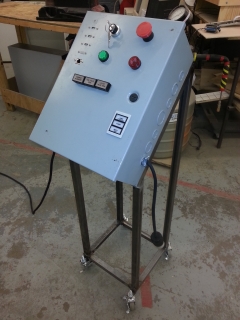
I had a plan for how to blog about this project, but I’m going to step out of order and talk about the latest development since it pertains to the last Fusion 360 Meetup. So to catch up in a hurry: I’ve already constructed a control box containing an Arduino Mega 2560 and a Raspberry Pi, power supplies, relays, etc. all mounted on DIN rails. This is the “brains” of the system, and the Pi runs an open source control framework called EPICS. The control box sits on a separate stand on wheels that I welded. In keeping with the “Beer Church” theme, I suppose this is the “Beer Pulpit”.
I realized early on that the control box was out of room. I want this brewing system to be modular so that I can attach different equipment and reconfigure everything via software. To that end, each device needs to connect to the control box with its own sturdy, detachable connector. The original BrewTroller project (which isn’t online anymore) made use of XLR jacks. These are ideal. Nearly every device I’m interfacing with uses 3 or, in some cases, 2 wires. The OneWire serial bus, which is used for measuring temperatures, uses a 3 pin M12 connector; these are chained together using splitters. A few use cases need more than 3 wires: multiple pressure transducers on one board (used for fluid level sensors) and stepper motor drivers (used for controlling gas needle valves). For these, I’m using 8 pin mic connectors. But I don’t have enough panel space on the control box for all of these jacks, especially now that I’m considering adding a small touch screen. Nor do I have room inside the control box to mount a 120 V to 24 V transformer; 24 VAC is a HVAC standard, and the propane burner valves need it.
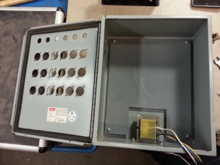
The solution: In addition to the control box, I’m adding an extra distribution box to the stand that will serve as an output panel and will hold the transformer. The two boxes will be connected by flexible cable conduits. But this leads to more problems. I have zero interest in drilling 54 precisely located holes for 18 XLR jacks on a drill press. I originally planned to use PS:One’s Bridgeport CNC mill, but it still isn’t functional after more than a year, and I had concerns anyway about how I could clamp it, or if I’d break end mills. Fortunately, my friend Peter Zieba of Analytics Lounge has access to an OMAX waterjet cutter. He used AutoCAD LT to lay out the panel according to a paper sketch that I made. He had a DXF of the proper panel cutout for an XLR jack. We did a test cut on a scrap piece of metal, and it fit perfectly. For the M12 and mic connectors, I used a digital caliper and estimated the size. We had to take out several slats from the waterjet bridge to fit the box, but ultimately it worked, and it produced excellent quality cutouts. The only issue: I sized the cutouts for the M12 and mic jacks too small, so some hand filing will be needed.
There’s engineering, and then there’s over-engineering. This entire project falls into the latter category. So while I now have everything I need to wire the panel, this got me thinking…. I’d like the option of separating the two boxes to work on them, but that’s problematic if I solder wires to an XLR connector on one end and crimp the other end along with a number of other wires into a cable assembly to attach to the Arduino. I need terminal blocks. I don’t have enough in my control box. Having terminal blocks in the distribution box would let me set up ground and power distribution buses more elegantly than having a horrible rat’s nest on the back of the panel. The inside back of the distribution box has standoffs for a plate to hold equipment, but unlike the control box, it didn’t come with a plate. So that means I need to fabricate one. Sure, I could use a shear, band saw, and drill press, but when you’ve got access to a fun waterjet cutter….
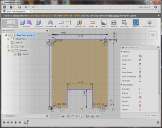
So I need a rectangular panel with four holes for mounting screws. The panel will mount DIN rails which I’ll use primarily for terminal blocks. I may make adapter plates to mount stepper motor driver boards on the DIN rail as well. The panel will need a cutout at the bottom for the transformer, which I’m mounting directly to the bottom of the box. Measuring the inside of the box was awkward; I had to use a tape measure, and it appeared the holes were spaced 8 1/4″ x 10 1/4″.
I know I’m dating myself, but the last CAD package I learned was for MS-DOS. I’d normally do a 2D layout like this in Adobe Illustrator or Inkscape. But two days prior, Michael Aubry hosted a Fusion 360 Meetup at PS:One. Michael is an evangelist for Fusion 360, and Autodesk has been flying him from Portland to Chicago to host these Meetups. It was supposed to be a hands-on intro class, but my poor laptop running WinXP was not up to the task, so I couldn’t follow along. I figured I’d try this at Analytics Lounge, so I installed Fusion 360 on one of their computers.
While Fusion 360 is a 3D CAD package, I only need to create a 2D DXF file to import into the waterjet. So I went into Sketch mode and drew the basic outline. I’d normally expect to type in coordinates or line lengths to draw everything. But instead, I just drew lines freehand, then dragged dimensions onto them. The rectangular cutout for the transformer needed to be centered. I’d generally expect to do math to figure out the length of each line. Instead, I just added a constraint that the two bottom edges on either side of the cutout have equal length. The result was practically magic. I could resize the part, or the cutout, and the cutout still stayed centered. I then created four guide lines, added dimensions so they would be equidistant from the edges of the panel, and placed the holes.
I ran into some trouble when I couldn’t find the screen that had a list of all the parameters containing dimensions that I saw Michael use in the class. And the class handout hadn’t been posted online yet. So I tried exploring the help system. I didn’t know what the screen was called. Typing things into the search box often pointed me at what appeared to be forum posts, and I couldn’t find what I needed. But I did find a collection of videos, selected one that looked promising, and watched it. I then saw that I just needed to go to Modify -> Change Parameters. Once finished, I could save a DXF of the sketch.
All in all, I’m very impressed with Fusion 360. Never having touched it before, it was surprisingly intuitive. And it really mirrored my mental process well. I’m all too familiar with needing to change one dimension and then having a massive amount of work to move everything else. But here, all I need to do is set constraints intelligently, and the design will correct itself whenever a dimension changes. I’m well aware that I’m just scratching the surface of its 2D capabilities; I’m very excited to use this for 3D and CAM.
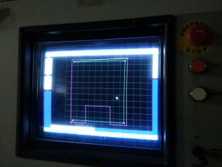
The waterjet software wasn’t as intuitive. Simply loading the DXF brought in my guide lines (that aren’t supposed to be cut), the circles, and nothing else. But there’s an Import DXF option which I needed to use to bring in everything. I then could manually select and delete the guide lines. While I normally don’t bother with lead-ins and lead-outs when using a CNC router, with a waterjet, this becomes more necessary. The jet has to pierce the material for each cut, and it is best if that doesn’t occur on a finished edge. Fortunately, the software was able to add the lead-ins and lead-outs automatically and compute a path. (This isn’t always the case, and the software wants to cut on the wrong side of the part.)
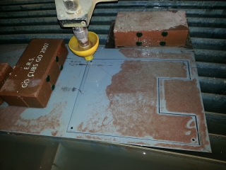
Cutting the part was a learning experience. We learned that positioning the nozzle too close to the part can result in the high pressure water shooting up the hose that carries the garnet abrasive, and then blowing the hose loose from the nozzle. Cleaning and drying the hose and the pneumatic valve assembly on the garnet hopper was an adventure. This happened partway through cutting my part, but fortunately the software allows the operator to start a job in simulation mode, pause, and then resume while actually cutting.
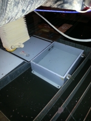
The final result fit inside the box perfectly. So I used Fusion 360, and I successfully made a thing. Hooray!
Update: Two videos of the waterjet cutting the control box:
