A first for me: designing a circuit board!
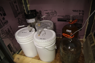
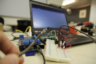
One of the more noble uses of electronics: enabling the production of beer. Chillmon is a concept originally created by Eric Stein to use a Raspberry Pi to control the fermentation temperature of beer at Pumping Station:One. It began life as a breadboard that used TMP36 sensors to record the temperature in the cabinet where we ferment, with Python code that graphed the output on a web page and responded to IRC queries with the beer temperature.
I donated an old window air conditioner to the effort, and, with the addition of a solid state relay and an enormous 120V contactor that could handle the motor load of the compressor, we had the Pi capable of turning the air conditioner on and off.
This also taught me the importance of pulldown resistors. As we found out the hard way, the Pi defaults pins to high impedance input mode, and the voltage can float high enough to trip a solid state relay. This caused the contactor to slam open and closed repeatedly, and fortunately we stopped it before we fried the air conditioner. A simple pulldown to ground is all we needed to stop this errant behavior.
So, to keep fermentation temperature steady, I wrote some C++ pseudo-code that Eric translated to Python, which implemented the PID industrial control algorithm. Every five minutes, it decides how long the air conditioner should stay on to reduce the error between cabinet temperature and target setpoint temperature. So this is extremely slow pulse width modulation. The air conditioner has a lot of chilling power, so much that it can easily get the cabinet below freezing. And it isn’t well insulated. So the temperature swings wildly. The solution: take a 5 minute average during the last control cycle, and use it to determine the error, hence the duty cycle for the next control cycle. It is surprisingly accurate, at least when the ambient temperature in PS:One’s shop is above the set point. And we are considering adding a heater to the fermenting cabinet for the winter months when we want to brew ales that need higher temperatures. Eric made the code available on GitHub.
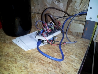
I had taken a class from Steve Finkelman on Eagle CAD and wanted to try designing my own board. The existing design, shown above, had a number of issues:
- It was on a breadboard, and wires could pull out.
- It used a 3.3V Vref with TMP36 sensors and a 10 bit ADC. The TMP36 really only needs a Vref of 1.0V, and, as a result, one bit on the ADC corresponded to nearly a degree F, limiting the precision of temperature regulation.
- I suspect that poor breadboard connections might contribute to variable voltage, causing noise to the temperature readings.
- A digital sensor like a DS18B20 would be far superior to a TMP36.
So I started by examining Adafruit’s Pi Plate. They make the Eagle CAD files available on GitHub, and also provide a seriously useful library of parts. It turns out they got the outline Pi shield from microBuilder.eu so I acquired the libary and got to work. Eagle CAD, I’d say, is user-friendly; it just happens to be picky about who it considers friends! And I was merely an acquaintance. But after some time, we built our friendship.
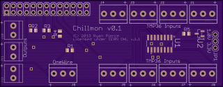
For the most part, the schematic was easy. I laid out an MCP3008 ADC using the same Adafruit tutorial that Eric used when originally creating the board, and added 8 input jacks using the same pretty blue terminal block Adafruit uses on their proto boards. Adding three digital outputs was easy, as they just needed pulldown resistors. The OneWire input for DS18B20 thermometers was easy too; I’d previously done work with this before for Arduino. It just needs a 4.7k pullup resistor. And the Adafruit Occidentalis distribution for Raspberry Pi supposedly has kernel support for OneWire; I just needed to connect it to GPIO4. The only new stuff for me was the idea of using an ADR510 1.0V precision voltage reference to supply a lower Vref to the ADC. So I added a jumper to select between 3.3V from the Pi, or 1.0V from the voltage reference; that way, if it doesn’t work, I can always use 3.3V and I’m no worse off.
Board layout proved more challenging, but eventually I got something I liked. Unfortunately the microBuilder.eu library had all the pin names for the Raspberry Pi connector on the tNames layer, which resulted in the silk screen for the board extending over the edge. So I copied the Pi component to my own library, modified it to move all that text to the Document layer which won’t print on the silk screen, and also resized the board. Seeing as I am paying OSH Park per square inch to produce this, there’s an incentive not to be wasteful.
The net result: $20.95 including shipping, which will give me 3 blank boards. I’ve purchased components from element14 and Adafruit, so I have enough to assemble three. Not including shipping, everything came to about $22 per board, including the board itself. I’ve received word that the board has already been sent to the board fabricator, and OSH Park will get it back on March 24. I’ve also uploaded the board design to GitHub.
I have absolutely zero experience with surface mount soldering. But everyone tells me it’s not that bad, especially since I’m just using 0805 resistors and an SOIC chip. More on that adventure once everything arrives….


