Design Sources
A number of commercially available and hobbyist-built computer controlled brewing systems already exist that solve many of the issues I mentioned in my previous post on this topic. They have a number of similarities, but address the problems in different ways. I’m going to describe a number of methods used for computer controlled beer brewing, which improve up0n repeatability by reducing deviations in the mash process. These systems range from simple thermostat / standalone PID controls to microcontroller-based devices. I’ll also list my own design decisions when building this system and my reasoning. Note that my design decisions aren’t necessarily best, there are plenty of valid arguments for and against many of the solutions presented here, and as I write this, I’m kicking myself for some of the mistakes I made along the way.
I’ve examined a number of systems. Our local homebrewing store operates one. I’ve paid particular attention to open source and published plans for hobbyists, given that these offer the most information. Two of my primary sources:
- Brutus Ten – Website here. Build pages here and here. This is a popular brewing system due to plans published in Brew Your Own. It consists of a welded steel frame and propane burners driven by standalone industrial temperature control modules.
- BrewTroller – The original website was oscsys.com which features an Arduino-based open software and control electronics framework for brewing. The website hosted the software, documentation, a web forum for users, and an online store where one could purchase electronics, actuated valves, switches, temperature probes, etc. It is not locked to any single brewing system design; rather, it is flexible enough to support a wide variety of brewing hardware configurations. While the original site shut down, a user took this over at this site.
Size Considerations
Often, size isn’t a terribly important consideration for brewing systems. People keep them outside their main living space, such as in their garage or basement, and pull them out when they need them. In this case, I’m designing this system with two size constraints. I intend this system to reside indefinitely at PS:One. We would use this in the loading dock, where we can open a garage door and have ample ventilation. But it would need to be stored in the kitchen, which has limited space. The more compact I can make this, the better. Additionally, I would like to be able to take this system to Maker Faires. And I don’t want to have to rent a truck. So I’m designing this to be portable enough to fit in the back of my SUV.
I grossly underestimated how the design decisions I originally made to make the system more compact would have adverse thermal consequences. Fellow PS:One member Fitter Dave helped me substantially in overcoming these issues, which I will discuss in a later post.
Kettle Configuration
Nearly all automated home brewing systems employ three kettles:
- Mash Tun – This kettle has a false bottom and holds the grain during the mash.
- Boil Kettle – This is where the wort goes when the mash is complete. This is where it is boiled and hops are added.
- Hot Liquor Tank (HLT) – This holds hot brewing water (don’t ask me why it is called “hot liquor” ) which is used to rinse the grain in the mash tun during sparging.
Reducing the system beyond this is difficult. During lautering, hot water will flow into the mash tun at the same time as wort flows into the boil kettle, so all three kettles are used simultaneously.
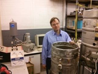
While there are a number of options for kettle construction, I am using 15.5 gallon stainless steel beer kegs. These are an ideal size for brewing 10 gallon beer batches. And several kegs were abandoned at PS:One for several years, so I claimed two of them. (I still have not constructed a boil kettle. The existing kettles Beer Church uses will be adequate for initial testing, although 10 gallon batches may not be possible.)
Heating
The main options for heating brewing kettles are propane, natural gas, or electric. We don’t have readily accessible natural gas that we can use at PS:One. While it is possible to make electric kettles using low watt density heating elements designed for water heaters, I worry that they can scorch a mash or a wort. Electric heating requires considerable power, usually 240V, or, at a minimum, multiple dedicated 120V circuits. I don’t want to build a system for PS:One that requires running new power feeds, and it would make it difficult to use the system outside of PS:One, say, if I transported it to a Maker Faire. So that leaves propane. It is convenient, inexpensive, and ubiquitous.
This system could work with two burners. As I’m building a HERMS system (described below), the mash tun maintains heat via the HLT. And the boil kettle needs its own burner. The mash tun, strictly speaking, doesn’t need a burner at all. But without a burner on the mash tun, I would have to do one of two things:
- Recirculate the water for the mash through the HLT heat exchanger to bring it up to temperature. This would be a slow process.
- Heat the water for the mash in the HLT. Drain it into the mash tun. Fill the HLT with sparge water. Bring it up to temperature. And this is necessary before adding grain to the mash, since otherwise there would be no way to add heat to the mash. Heating both kettles sequentially would be slow.
So I decided to add a third burner to heat the water in the mash tun, even though it will only see use prior to adding the grain for the mash. This will allow me to heat both the mash tun and HLT at the same time.
For burners, the two primary choices are:
- Cast iron banjo burners, which draw air into a venturi to mix with the propane prior to entering the burner.
- Jet burners. These use brass nozzles, and air mixes with the propane in the jet tip.
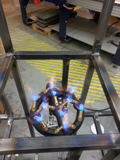
Jet burners can provide a lot of heat. I wanted to make sure I had enough. And, well, they look really cool, so I bought three 8″ 92,000 BTU low pressure propane jet burners. Now I have heard complaints that the sealant used on the jets can break down with heat and leak, causing little flames where the brass screws into the casting. Tightening them is the wrong answer; it strips the threads. I have heard one can use better high temperature sealants. But to date, I have not noticed any problems with them.
Next, a microcontroller will need a way to command the three burners, and they need an ignition system. First, I strongly dislike the method used by the Brutus Ten. Each burner has a pilot light that is always lit. But the pilot light gas gets supplied by a needle valve. If the pilot light blows out, that would be bad. An actuated valve controls the burner in the Brutus Ten. This has three problems: First, the specific model might have been cheap for the person creating the system due to a lucky eBay find, but it is fairly rare, and when I looked, the valves were several hundred dollars each. Second, based on the specs I’ve seen, I don’t think the valve is rated for low pressure propane. Third, since the electronics have no idea if the pilot light is lit, they can turn on the propane for the main burner anyway. Blowing up the hackerspace is frowned upon. So, no.
A higher tech solution has no pilot light but uses electric ignition. This requires high voltage to make sparks to ignite the burner. I’ve heard this can also introduce considerable electrical noise.
I settled on a much simpler solution. Honeywell makes standing pilot gas valves that are widely used in furnaces and hot water heaters. These use a pilot light burner, and they have a thermocouple in the flame of the pilot light burner. If the pilot light goes out, the thermocouple gets cold, the pilot light gas turns off, and the main burner refuses to open even if commanded to do so. This is a much safer approach. Like much HVAC equipment, this uses 24 VAC, so I need the microcontroller to control a relay, and a simple transformer to step 120 VAC down to 24 VAC. I am installing a normally closed, 2 pole Emergency Stop button on the panel. One pole will be in series with the 24 VAC burner controls, so even in a worst case software failure I can easily stop the burners.
An important note: natural gas and low pressure propane operate at different pressures. The Honeywell parts include conversion kits. I had to disassemble parts of these valves, replace a spring, and reassemble them. And the pilot light came with two different nozzle size inserts, one for natural gas and one for propane. Switching these is important.
Next, there’s the question of controlling the intensity of the flame. The Honeywell controller just turns the burner on or off. Burner controllers for high efficiency furnaces that provide low vs. high flame settings are expensive. Actuated needle valves I’ve found that can control the gas flow rate to the burner are ridiculously expensive. So I decided to put 1/2″ NPT Parker instrumentation needle valves between the burner controller and the propane burner, so I can control the intensity by hand. In a later phase of this project, I will want to attach stepper motors to the valve stems, making my own actuated valves, so the microcontroller can adjust flame intensity.
Kettle Filling and Fluid Level Instrumentation
While we do all our brewing with unfiltered tap water today, I intend to pass city water through a sediment and carbon filter to remove chlorine. (Reverse osmosis systems would be a terrible idea in Chicago; the mineral profile is perfect for brewing and I don’t want to change this.) To automate filling the mash tun and HLT with the right quantity of water, I’m adding fill spouts at the top of both kettles, with a solenoid valve and a flow rate sensor. The sensor generates a series of pulses, which I am attaching to hardware interrupt pins on an Arduino. Correlating pulses to water volume will require calibration, but once that is done, the system should be able to open the solenoid valve, let a programmed amount of water flow into the kettle based on the beer recipe, and close the valve. I have not experimented with this yet, but I hope it will be repeatable and accurate.
I also intend to add fluid level sensors in the mash tun, HLT, and boil kettle. These will be steel tubes, open at the bottom, extending nearly to the bottom of each kettle. An aquarium pump will pressurize a manifold with needle valves, and each will be adjusted to bubble a small amount of air out of each tube. Each of these air lines will attach to an air pressure transducer. This design came from the original oscsys.com website, and they sold boards that included the transducers. Calibration will be needed to correlate liquid volume to resulting pressure, but these should allow for easy measurement of fluid levels in each vessel. This could be used for:
- Cross checking the flow rate sensors during water fill, and replacing them if these prove more accurate.
- Measuring the progress sparging.
- Measuring and controlling the amount of sparge water added to the mash, or when to stop the sparging because enough wort has been collected.
- Measuring the boiloff rate. (I question how well this would work, and whether an algorithm controlling the needle valve can control the boiloff rate.)
Experimentation will be needed to determine if fluid levels of wort can be measured accurately.
RIMS and HERMS
Controlling mash temperature is critical. But simply using a metal mash tun and heating it directly to compensate for heat loss, and increasing the temperature for a step mash schedule will likely result in scorched grain and wort. Vorlauf can solve this problem. Continuously recirculating the wort during the entire mash process allows precise mash temperature regulation, step mash schedules, and will result in a clearer wort in the brew kettle. Two common homebrew methods that use vorlauf to regulate temperature are RIMS and HERMS.
RIMS is Recirculating Infusion Mash System. With RIMS, one uses a pump to recirculate wort from the false bottom of the mash tun, through a pump, and back to the top of the grain bed. Brutus Ten is a direct fired RIMS system, where the propane burner under the mash tun fires to raise temperature. In theory, the pump provides fluid movement, which circulates the heat through the grain bed. Another common RIMS approach places a “RIMS tube” after the pump. Wort flows through a tube with contains an electric water heater element that can add heat. In both cases, the heat could scorch the mash and/or wort, but the constant recirculation should, in theory, prevent this. The latter form of RIMS uses high wattage AC, which as I mentioned above, I’d prefer not to do. Both trust in recirculation flow to prevent the grain from scorching, which could cause problems if, for some reason, the mash sticks.
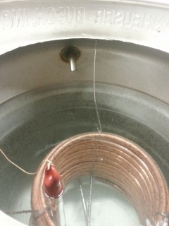
HERMS is Heat Exchanged Recirculating Mash System. With HERMS, the pump recirculates the mash through a coil located inside the HLT that acts as a heat exchanger. Controlling the temperature of the HLT water via the propane burner will control the temperature of the wort leaving the heat exchanger. This has a significant advantage over RIMS: the wort never touches direct heat from either the bottom of a kettle or an electric heating element, so even if recirculation stops entirely, nothing can scorch. I am using the HERMS approach, with nearly fifty feet of copper refrigeration tubing located inside the HLT.
Sparging and the Brew Sculpture
The frame holding the kegs, often made of welded steel, is called a “Brew Sculpture.” The design of the brew system influences the sculpture design. All RIMS and HERMS systems require four fluid flows:
- During the mash, wort must recirculate from the bottom of the mash tun, optionally through a heat exchanger or RIMS tube, to the top of the mash tun.
- At the end of the mash, wort must flow from the mash tun to the boil kettle.
- At the end of the mash, sparge water from the HLT must flow to the top of the mash tun.
- At the end of the boil, the finished beer wort must flow from the boil kettle to the fermenter.
The fourth can be accomplished with gravity, as the boil kettle will be higher in the sculpture than a fermenter set on the ground. If the HLT, mash tun, and boil kettle all have the same height, then the first three can be accomplished with two pumps: one pump from HLT to mash tun, and another from mash tun through a two way valve either back to the mash tun or to the boil kettle. However, I’ve designed my brew sculpture to keep the HLT above the mash tun and boil kettle. That way gravity can transport sparge water to the top of the mash tun. So I will only need one pump and a two way valve.
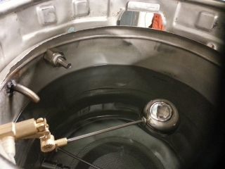
Controlling the rate of sparge water flow into the mash tun is necessary to prevent the mash tun from overflowing or running dry. I am using a Blichmann AutoSparge. This utilizes an adjustable float valve which opens as the water level in the mash tun falls.
Grant
Using a pump to recirculate wort in a RIMS or HERMS system can introduce problems. The pump can exert suction on the grain bed, compacting it. The pump uses a magnetic drive, so an actuated ball valve on the output of the pump can control flow rate. But a more ideal solution is to introduce a small additional vessel into the system, called a grant. The grant might as well be a bucket with a hole in the bottom. An actuated valve on the mash tun controls the flow rate that wort fills the grant. The pump empties the grant. As the grant is open to the atmosphere, the pump applies no suction on the mash tun. However, the pump cannot be run dry without damage. This is an ideal area for a fluid level sensor. A control algorithm could potentially adjust valves to maintain a safe level of wort in the grant, and to shut down the pump if it were in danger of running dry.
I plan to fabricate a grant out of a stainless steel fire extinguisher that Fitter Dave donated. But I will add this only at a later phase of the project.
Temperature Monitoring
The BrewTroller project uses OneWire temperature probes. I already have experience with these, specifically the DS18B20 sensor. OneWire is a simple serial bus, similar to I2C but without a separate clock line, and is easy to bit bang using a microcontroller. This temperature probe can capture and digitize a temperature in 750 ms, readable to 1/16 degree Celsius. Many probes can be chained together on a bus, with each probe individually accessible via a unique address. The controller can issue a broadcast command to cause all sensors to capture the temperature, and 750 ms later poll each one in turn. oscsys.com sold these in 1/4″ sealed stainless steel tubes, using M12 electrical connectors.
List of Physical Controls and Sensors
I’ve arrived at the following list of devices that will need to be controlled, and am including a flow diagram to illustrate this.
Mash Tun
- Solenoid Valve – Cold Water Fill
- Actuated Ball Valve – Wort Drain
- Blichmann AutoSparge (manually adjusted, not computer actuated)
Pump
- Pump Motor (120V, switched via relay)
- Actuated Ball Valve – to control pump flow rate
- Actuated Two Way Ball Valve – to switch between recirculating wort or filling the boil kettle
HLT
- Solenoid Valve – Cold Water Fill
- Actuated Ball Valve – Wort Drain
Boil Kettle
- Â Actuated Ball Valve – Wort Drain
 Burners
- 3x Standing Pilot Gas Valves (24 VAC)
- 3x Needle Valve (burner throttle, initially manually adjusted, controlled by stepper motors in a later phase)
The following sensors will provide data to the microcontroller:
Temperature
- Mash tun – mash temperature
- HLT – water temperature
- HLT – wort temperature exiting heat exchanger
- Boil kettle – wort temperature
- I may add additional temperature monitoring for cooling water input and exit temperature, and wort output temperature, for a wort chiller.
Flow Rate
- Meter on mash tun cold water fill
- Meter on HLT cold water fill
Pressure
- Mash tun fluid level
- HLT fluid level
- Boil kettle fluid level
- Grant fluid level


